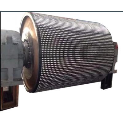
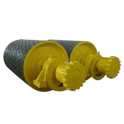
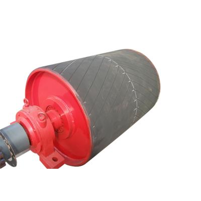
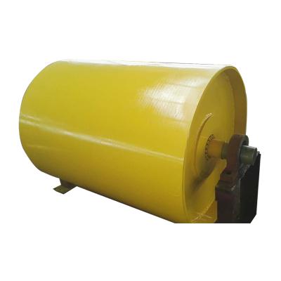
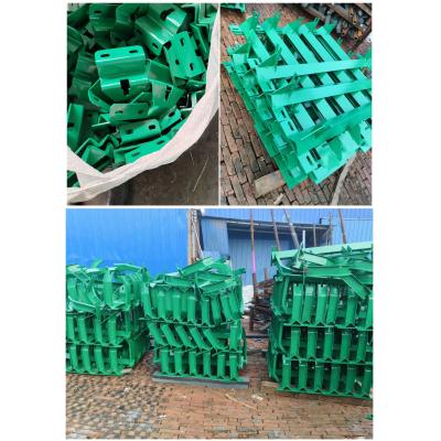
Hydraulic Conveyor Frame
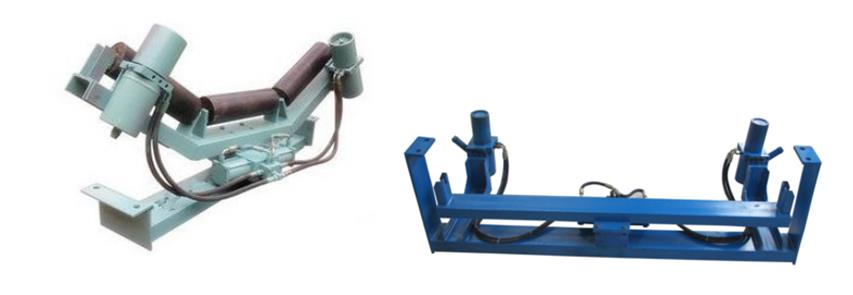
Working Principle
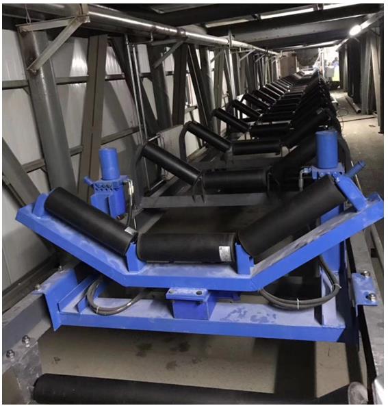
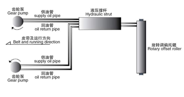
Two vertically-mounted drive wheels are arranged at the same height on both sides of a set of aligning idlers on the frame. The drive axle is connected with oil pump power input shaft. Fix the left and right inspection wheel and oil pump on the self-aligning roller bracket with two fixed brackets, The tail of the compound cylinder is hinged with the fixing bracket, The piston rod of the composite cylinder is connected with the rotating part of the roller support of the aligning roller.Connect the oil port of the oil pump and the end of the compound cylinder with the oil pipe.
When the belt deviates to the left, touch the oil pump on the left side of the left inspection wheel to quickly output the pressure oil, and the oil manifold integrated block of the compound oil cylinder enters the rodless cavity of the oil cylinder to push the piston and the piston rod; The hydraulic oil with rod cavity is returned to the tank of the oil cylinder by the oil circuit integration block, The piston rod popped out quickly, Push the aligning roll clockwise (i.e. the left side of the aligning roll forward) to drive the belt to the right and center.
When the belt running deviation to right will touches the right test drive wheel, Right side pump output pressure oil, The manifold block through the compound cylinder enter into the oil tank of the cylinder, Piston rod quickly retracts, Pulling the counter-clockwise rotation of the aligning roller (deflection of the aligning roller) drives the right side of the fixing bracket of the aligning roller to set the compound cylinder belt to the left side and center.
Applications
